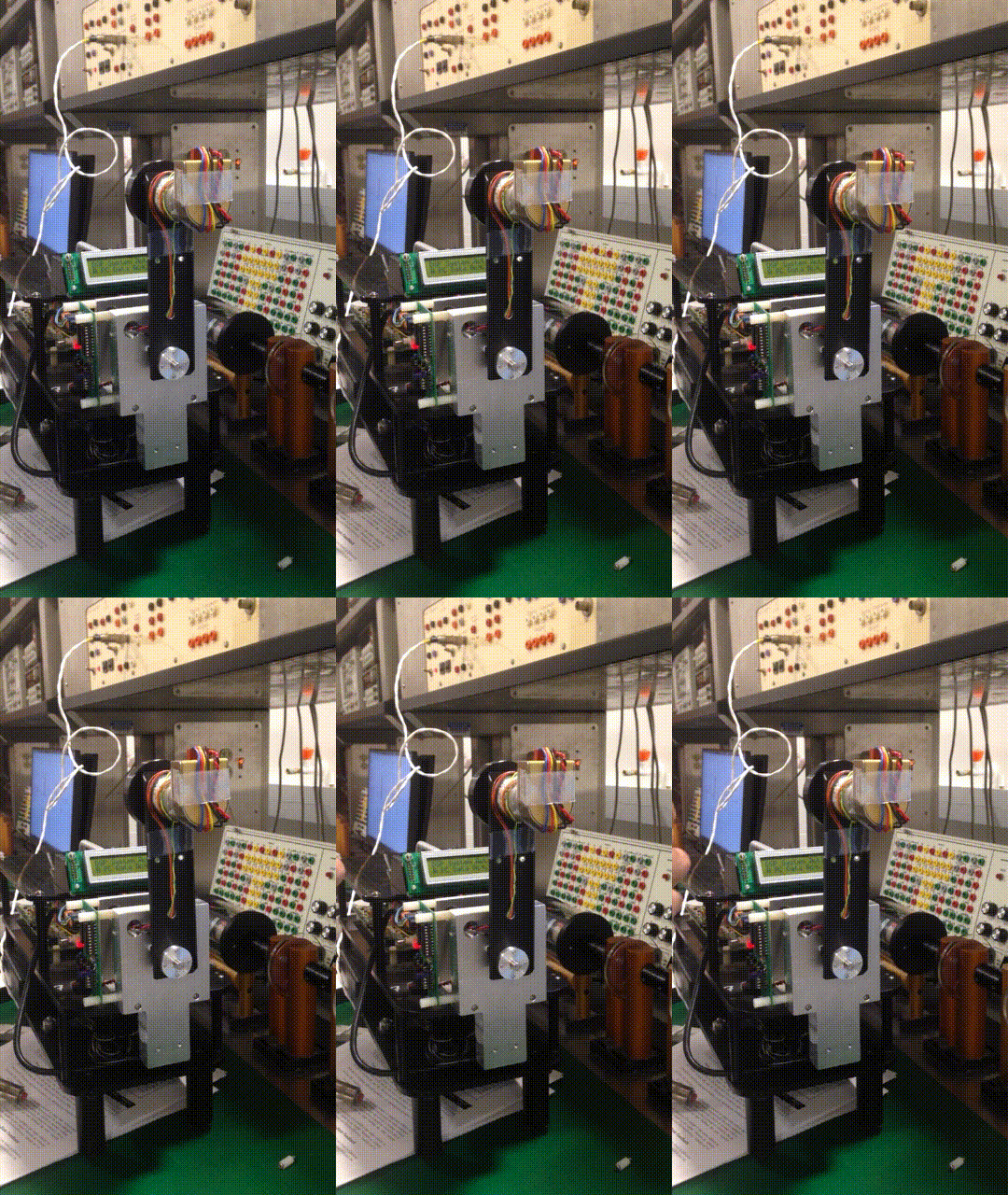
Reaction Wheel Pendulum
Course Project


The final project for the Control Systems course was to implement a controller to balance a Reaction Wheel Pendulum at it’s vertical positional. Various controllers were implemented- 3- State, 4-state and a 4 State using an observer. The states that were controlled were pendulum angle, pendulum velocity, rotor angle and rotor velocity. The controller was designed in Simulink. The electronics provided allowed the user to read the pendulum and rotor position and send an input to the motor.
- First, the system’s equations of motions were derived using a Lagrangian approach. These equations related the above 4 states via 2 equations.
- Before implementing a controller, the DC Motor’s friction model, torque constant, natural frequency, and other miscellaneous constants were identified by system identification techniques.
- The friction model was determined by implementing a PI controller where the steady state control effort was equal to the friction of the system. These values were recorded multiple positive and negative rotations to generate a linear curve for the friction model whose slope and Y- intercept were the dynamic and static column friction respectively.
- The torque constants were determined by running the motor at different velocities and measuring the values of different states. Using the motor equations that were developed, these constants could be calculated by direct substitution.
- The RWP is inherently a non linear system. To develop a controller for the vertical position, the system was linearized using a first order Taylor approximation. The resulted equations could be represented in the standard state space form of d(x)/dt=Ax + Bu and d(y)/dt=Cx + Du.
- All the controllers implemented were closed loop controllers of the form u=-K.x. K was determined using pole placement techniques for a state space system. Since this was a second order system, the response characteristics could be modeled through a standard second order system with a given damping factor and natural frequency. The damping factor and natural frequency were manually tuned till the RPM achieved limit cycle behavior.
- The 3 state controller controlled the pendulum angle, velocity and rotor velocity. The 4 state controller controllered all the states. Naturally, the 4 state observer was more sensitive to disturabcen and an initial velocity because it had to control an additional state.
- In the real world it is common to not have access to all of the systems state. In such a case a dynamic observer controller is used. For this RWP, it was assumed that the velocity states were no measurable. An observer was developed through observer design techniques for state space systems where the poles of the observer were placed 8 times further than those of the system. The observer input was the system’s input, pendulum angle and rotor angle. As expected, the observer design was even more sensitive to disturbance. This was merely an exercise to demonstrate the idea of building an observer.
- For the final demo shown in the video below, swing up control was implemented that added energy to the RWP till it reached close to its vertical position after which the controller took over.
Checkout the controller in action here!