UR3 Manipulator
Course Project


The final project for the Introduction to Robotics course was to program a UR3 robot using ROS (Robot Operating System) to pick up an object using camera vision via a suction cup attached to the end effector of the robot arm and drop at it a user specified location.
- First, two publishers and one subscriber were set up in ROS to control the suction gripper state, control joint angles and receive the robot’s joint angles respectively.
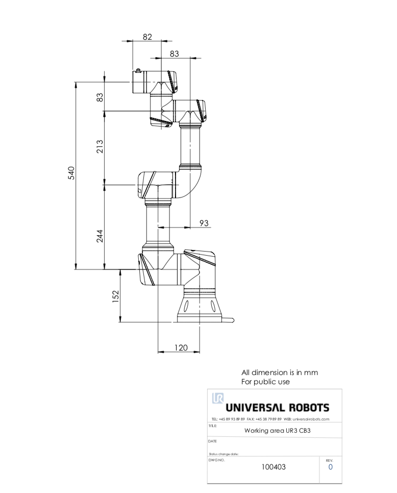
- Using the robot’s data sheet the forward kinetics of the robot were calculated to determine the end effector position all the given joint angles.
- Therefore, once the joint angles of the robot were received, the forward kinematics could be calculated to check if the end effector in the correct location or whether the system should wait for the robot to reach its commanded position.
- Next, to reach a desired state the joint angles to reach that state were required. To solve this inverse kinematics problem, geometrical constants of the robot were exploited and a set of equations were generated to calculate the the joint angles given a desired end effector position. To simply calculations, the end effector’s mount or theta 7 was made equal to 0 degrees.
- The robot was now capable of changing its a joint angles to make the end effector reach a desired location. Note that by limited the workspace of the robot, singularities were avoided and could not be reached.
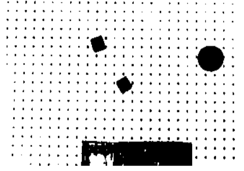
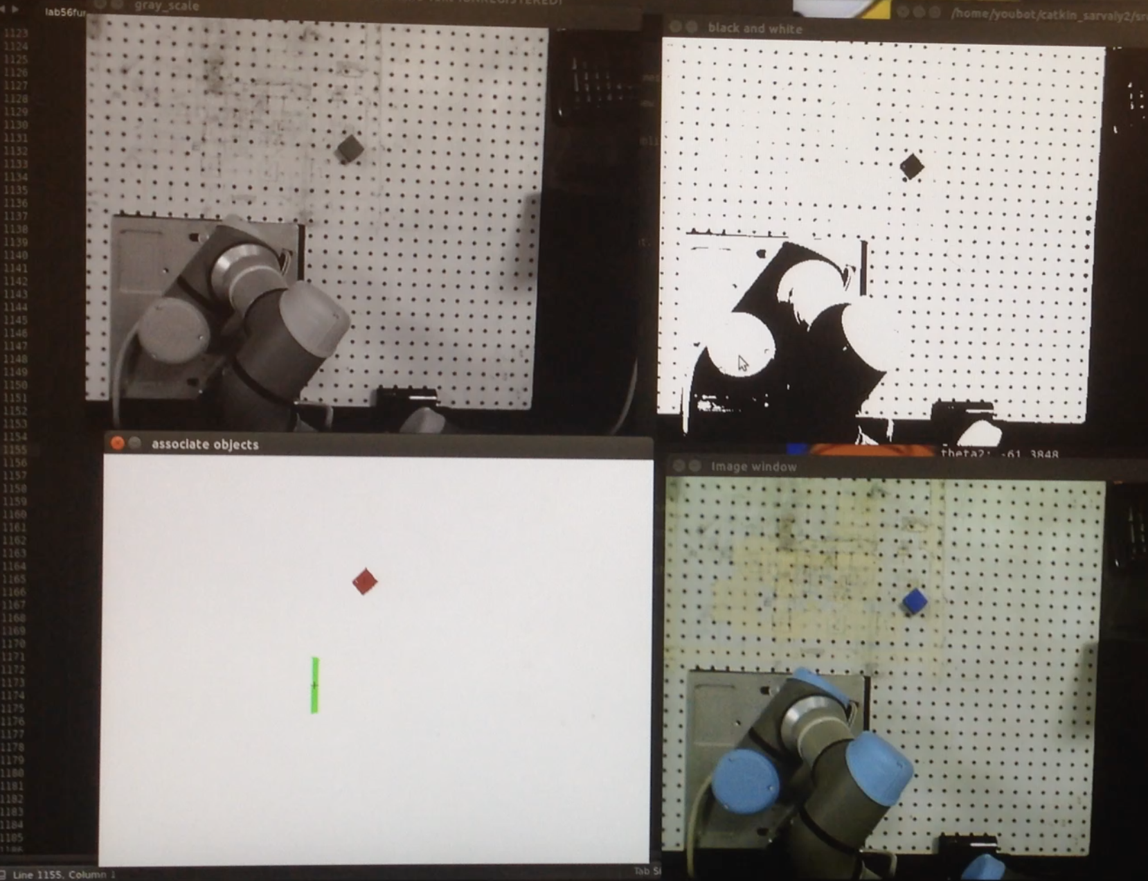
- On the vision processing side, the goal was employ a segmentation algorithm to separate the background from the colored blocks. An easy way to do this would be to manually tune the gray threshold levels to allow the colored blocks to pass but a more robust approach was taken. ince the blocks were brightly colored in comparison to the background, the image could be divided into two components by selecting a threshold value that minimized group variance. The image was then divided into a black and white image as seen in a figure above.
- To be able to pick up individual blocks, the robot must know their individual centroids. A labeling algorithm based on 4 point connectivity was implementing to divide the image into distinct objects. Objects that contained lesser than a certain number of pixels were rejected into the background (This parameter was manually tuned based on the average number of pixel present in a block).
- This image was now post processed to calculate each objects image plane centroid and draw a cross hair on each of their centers. This post processed image can be seen above.
- Since the inverse kinematics required an end effector position in world coordinates, the image plane coordinates had to be converted to this frame. Since process was simplified by making the pin hold assumption and positioning he camera was positioned such that its z axis was parallel to the world’s z axis.
- Finally, by combining the intrinsic projection equations and extrinsic rotation and translation equations, given an image plane centroid location, that point’s world cooradinates could be calculated.
- For the final demo which can be seen in the video below, the user can left click on a block to pick it up and right click on any location to drop the block there. To utilize the calculated centroids, every time a user clicked on a block, the program searched for the object centroid that was closed to that point and solved the inverse kinematics problem for that closest centroid.
Checkout our final project video here!