Advanced Controls Laboratory (UIUC)
Research Assistant


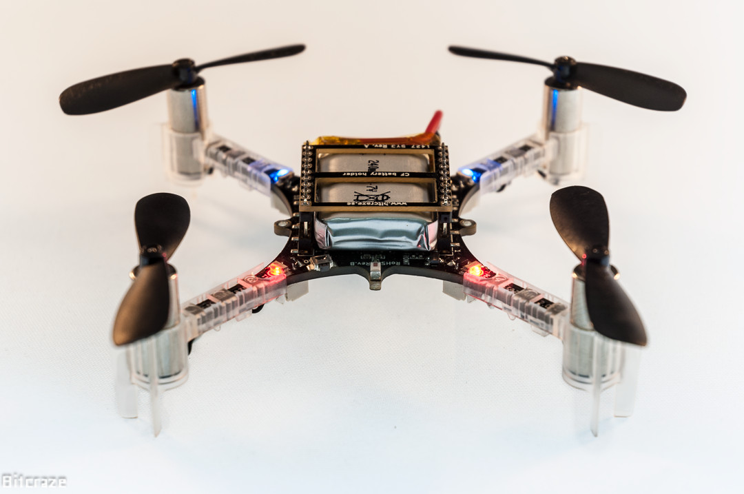
Servo and DC Motor are widely used in industrial as well robotic applications as precise positional controllers. The accuracy and dynamics of a motor varies widely dependent on the type of DC Motor, Sensors and Controller logic and Hardware used. The quadcopter in development at this lab will be fitted with 4 arms whose position will be controller via DC-motors. The servo motor previously used was bulky, over speced and its dynamics were unknown. My project was to first find a DC Motor suited to the drones requirements, fitted with a encoder resolution of higher than 0.4 Degrees/Count and prototype a controller through which the motor’s position, velocity and torque can be controlled. Once this is completed, a high fidelity model of the system will be determined such that the system can be simulated in Simulink.
Next, to gauge the dynamics and current, which indirectly measures torque, an observer design in state space will be built. After this system is rigorously tested, a more compact micro controller will be picked and the circuit will manufactured on a printed circuit board.
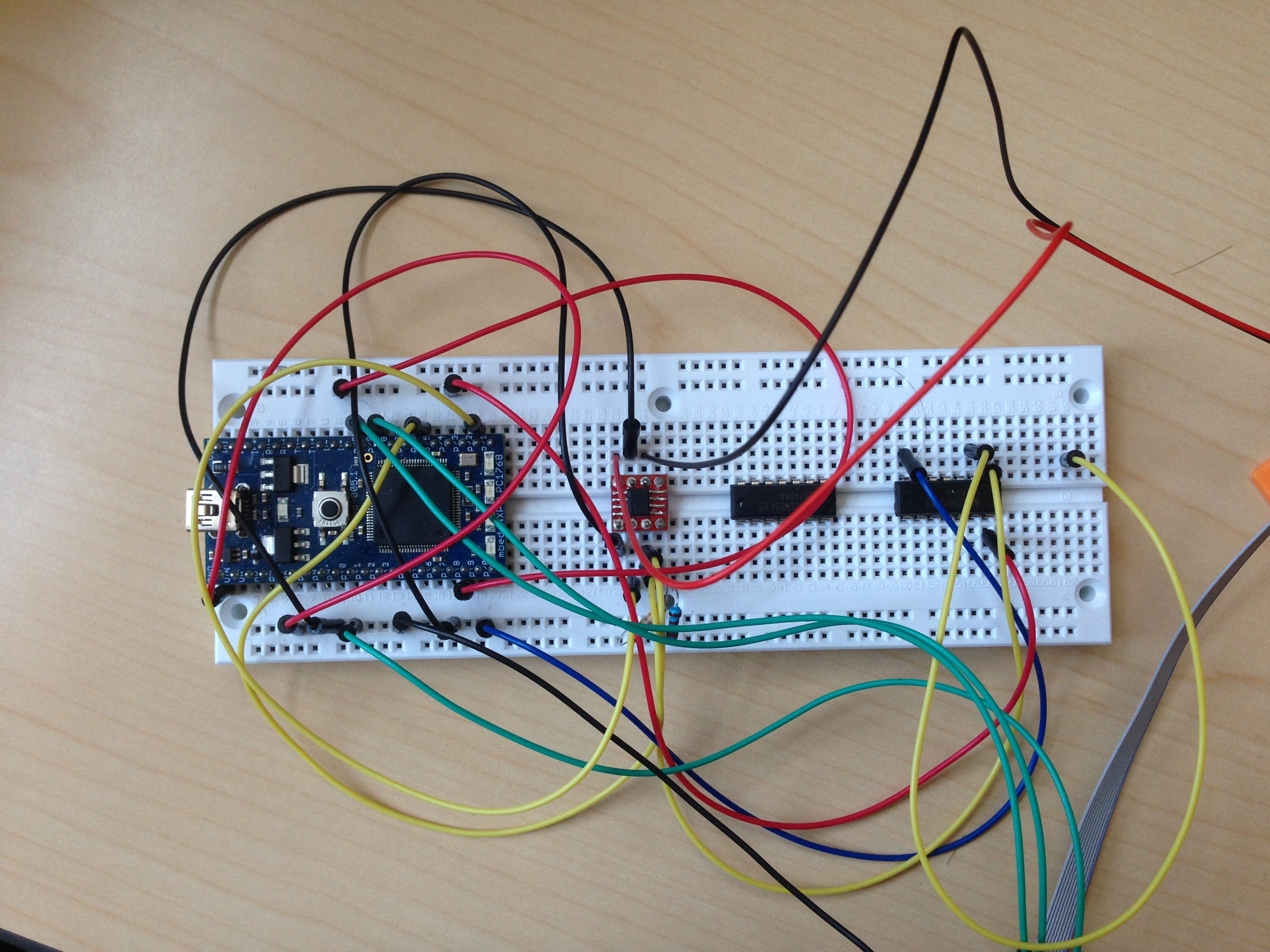
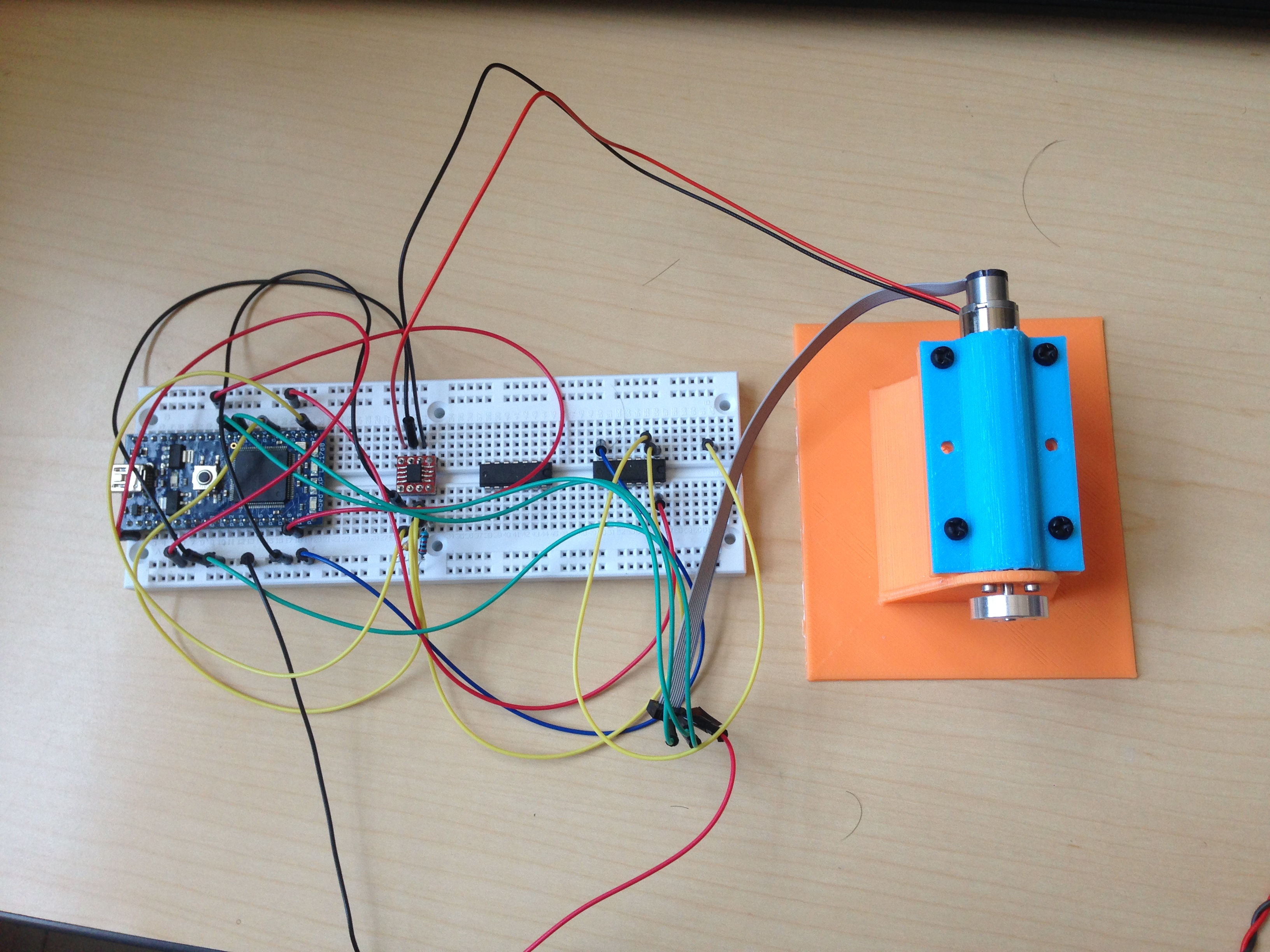
After extensive research and careful consideration of the requirements, a Maxon DC Motor was purchased. As for the hardware, a mbed developer board, TI- DV883071 motor driver, and TL7071 Inverter chip were chosen. Note that this set up will only be used at the developing and prototyping stage. The final model will be replaced by a more compact microcontroller and will be manufactured on printed circuit board.
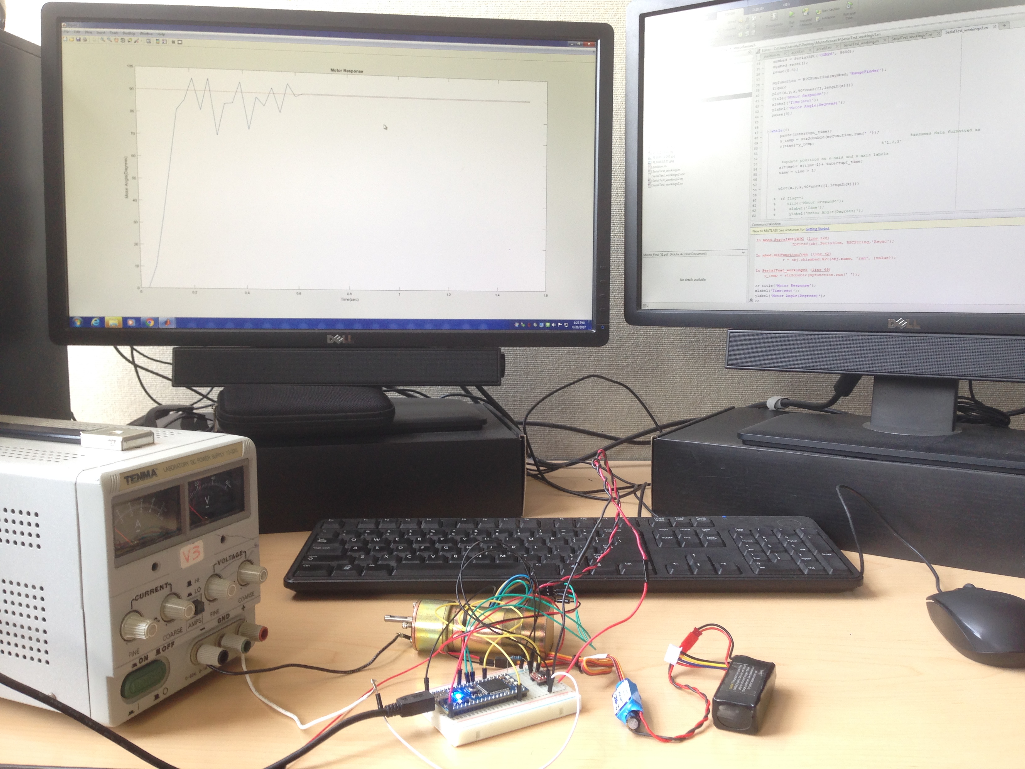
Next a mount was built to support the motor to ensure stability. After developing the code the control the motor’s position and velocity, a data acquisition needed to be programmed. Utilizing mbed’s Matlab connectivity, a program was developed that sent Matlab encoder readings during an interrupt service routine with a specified frequency. Additionally, to aid in manually tuning the microcontroller, a program that allowed the user to control variables on the mbed, namely the PID constants, through Matlab was programmed.
To capture the system’s dynamics, a 3rd order transfer function and State space model of the system was determined through experimental testing and using Simulink’s
System Identification toolbox. This model was also compared to one derived through the equations of the electrical loops of dc motor and using the values provide in the motor’s data sheet. To increase accuracy the data used for calculation was sampled at 1 KHz. After verifying these results by comparing the simulations to experimental data for a step response and various PID control modes, a state space observer was built that estimated the current and hence indirectly measuring the torque on the system. This paved the way to allow for torque control without the need of sensors.